Knowledge of thread taps
Time:
2024-05-20
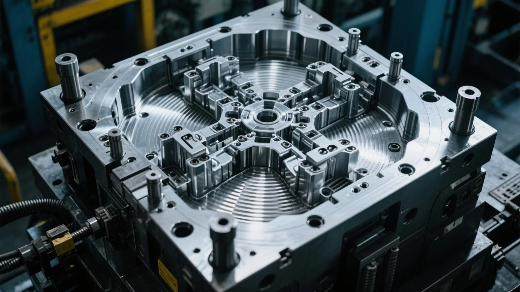
Basic Knowledge of Screw Forming Dies and Solutions to Common Machine Adjustment Problems
I. Basic Knowledge of Screw Forming Dies
1. Infeed Zone: This is the part where the wire is fed into the clamping area during machine adjustment. To facilitate feeding, anti-slip teeth are often engraved in the infeed and shaping zones.
2. Shaping Zone: This is where the wire is squeezed and shaped after passing through the infeed zone.
3. Forming Zone: This is where the wire is pressed into a screw shape according to the grooves, threads, and point angle of the die after passing through the infeed and shaping zones; 4. Discharge Zone: The part where the formed screw is discharged.
4. Back Angle, Elevation Angle: These are the parts where the wire is cut and the tip is formed in pointed dies. The back angle is key to controlling the amount of material fed into the tip; a larger back angle means more material, and a smaller back angle means less. The elevation angle is key to forming the tip and the thread on the tip. If the elevation angle is too low, it will cause dragging, and the tail will not be cut cleanly; if it is too high, it will cause the tip to break and the wire to be cut prematurely.
5. Cutting Edge: The part where the back angle and the tip of the die meet. The cutting edge must be very sharp; if it is too dull, the material will not be cut cleanly, causing dragging and inconsistent tip formation.
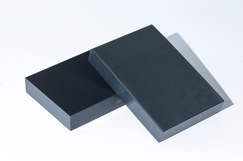
6. Thread Depth: The depth of the screw thread, which is key to controlling the outer diameter of the screw.
7. Thread Angle: The angle of the screw thread. Special screws have special thread angle requirements: C/B fiberboard nails have a 40-degree thread angle; BA round-head screws generally have a 47.5-degree thread angle; general self-tapping screws with a triangular double thread generally have a 45-degree thread angle; general machine screws have a 58-60 degree thread angle. The thread angle is also key to controlling the outer diameter of the screw.
8. Point Angle: The angle of the screw tip. General self-tapping screws typically have a tip angle between 40 and 50 degrees; special screws have special requirements, such as: wallboard nails and fiberboard nails generally have a tip angle between 20 and 30 degrees; machine screws generally have a tip angle between 80 and 90 degrees; sometimes the customer will specify the tip angle.
9. Chamfer: This refers to the sharp, pointed milling of the infeed and shaping zones during die production to facilitate material feeding. If the chamfer on the shaping zone is too sharp, the die will not be durable; if it is too dull and the surface area of the tail infeed zone is too large, it will be difficult to form the screw, and the outer diameter will not be large enough; if the chamfer in the infeed zone is worn too much, it will easily cause insufficient screw formation and an insufficient screw diameter, leading to slippage.
10. Anti-slip Teeth: These are the teeth engraved on the infeed and shaping zones of the die to prevent slippage during wire feeding and forming. If the anti-slip teeth are too shallow, it will cause slippage; if they are too deep, it will easily cause the screw base to be rough, the threads to be dull, and even blockage of the wire, resulting in a smaller screw outer diameter.
11. Point Height: The distance between the die surface and the cutting edge, generally half the screw base diameter. If the point height is too high, it will cause the screw cutting edges to collide, resulting in insufficient screw formation; if it is too low, it will cause the tail to not be cut cleanly, resulting in dragging.
II. Solutions to Common Troubleshooting During Machine Adjustment:
1. Common Problems
1) Broken Tip
2) Dragging (including flat tail, sharp tail)
3) Thread at the tail does not adhere, burrs present
4) Double Thread, Irregular Thread
5) Rough Base
6) Insufficient Outer Diameter
7) Excessive Outer Diameter
8) Slipping
9) Head Scratching
10) Broken Thread
11) Not Durable
2. Common Problem Analysis and Solutions:
1) Broken Tip: a. Severe broken tip - generally caused by an excessively high elevation angle on the die. Simply use a diamond file to lower it slightly (it is best to sharpen the anti-slip teeth) and then test the die. Repeat this process several times until the problem is resolved; b. Slightly broken tip - generally caused by three reasons: 1. The groove on the elevation angle is not open enough, use a triangular diamond file to open it slightly along the groove; 2. The elevation angle is slightly high, use a diamond file to lower it slightly; 3. The anti-slip teeth on the elevation angle are not deep enough or the elevation angle is worn too much, use a punch to sharpen the anti-slip teeth into a "-" shape on the grinding wheel. c. Broken tip can also be caused by excessively hard wire material, in which case the wire material needs to be improved. d. Broken tip can also be caused by the screw being too large and the wire being too long, in which case the wire length needs to be controlled.
2) Dragging: a. Sharp Tail: The tip of the screw has a needle-like tail that is not cut cleanly. This often occurs when forming screws with a very sharp tip, such as wallboard nails. The solution is to use a diamond file to sharpen the cutting edge along the back angle, facilitating material cutting; b. Flat Tail: A large amount of material is not cut off at the tail. This is generally caused by the following reasons: 1. The groove on the elevation angle is too wide or deep, resulting in excessive material feeding; 2. The back angle is too small, resulting in excessive material feeding. In both cases, use a diamond file to push the back angle inward along the back angle, increasing the back angle and reducing material feeding. Generally, the first reason is more difficult to repair, while the second is relatively easier; 3. Loosening the die during adjustment to reduce material feeding at the tip can also solve the dragging problem. For example, loosening the infeed end and tightening the shaping zone can also solve the dragging problem; 4. Controlling the wire length is also very helpful in solving the dragging problem.
3) Burrs on the Tail Thread: The cause and solution are the same as for dragging. Controlling the wire length is particularly helpful in solving the problem of burrs on the tail thread.
4) Double Threading: Generally, there are several situations: a. During machine adjustment, the tooth patterns are not well aligned. The screw thread is easily double threaded due to loosening and tightening during the extrusion molding process. Try moving the upper and lower plates several times; this usually solves the problem. b. If the two tooth plates are not placed on the same side during machine adjustment, uneven extrusion will easily cause double threading. c. If the gap between the sliding surfaces of the moving plate machine is too large during machine adjustment, excessive shaking during extrusion will easily cause double threading. d. If the feeding area is pressed too tightly during machine adjustment, it will easily cause double threading. e. If the anti-slip serrations on the tooth plate are too deep, use a triangular diamond file to smooth the burrs on both sides of the tooth groove along the direction of the tooth groove to reduce friction. f. If the chamfer width and depth of the two tooth plates are inconsistent, the tooth plates can only be returned to the manufacturer for repair (this situation is rare).
Rare.
5) Rough Base Diameter: The reasons are basically the same as double threading, except that the fourth reason, the feeding area being pressed too tightly during machine adjustment, accounts for the absolute majority. It is recommended to loosen the feeding area and tighten the forming area during machine adjustment. This should significantly improve the screw base diameter, outer diameter, gloss, and tooth plate service life.
6) Insufficient Outer Diameter: a. The anti-slip serrations in the tooth groove feeding area and shaping area have an impact on the screw forming. Within 0.04MM, it is recommended to use a triangular diamond file to smooth the anti-slip serrations along the direction of the tooth groove, which will have a certain impact on the tooth diameter. b. Within 0.04MM, use a slightly looser feeding area and a slightly tighter forming area during machine adjustment, which will have some impact on the outer diameter. c. If the machine is adjusted too tightly, the tooth length will be squeezed longer, and the outer diameter will naturally become smaller. This can be solved by loosening it slightly. d. If the outer diameter still does not meet the requirements after trying the above methods, it means the tooth groove depth is insufficient, and the tooth plate should be returned to the manufacturer for repair. e. If the tooth plate is excessively worn and the outer diameter cannot be reached, consider whether it has reached its service life. If it has, it can be scrapped; if not, it can be returned to the manufacturer for repair.
7) Excessive Outer Diameter: This is generally caused by a too-deep tooth groove. a. Within 0.05MM, use an oilstone or diamond file to reduce the forming area of the tooth plate by 0.01~0.02MM to solve the problem. b. If the outer diameter is too large, analyze whether the screw is too large and exceeds the tolerance, and whether the main mold is worn too quickly. Replace the mold if necessary. c. If the problem cannot be solved by the above two methods, return the tooth plate to the manufacturer to reduce the tooth depth.
Analyze whether
the screw is too large and exceeds the tolerance, and whether the main mold is worn too quickly. Replace the mold if necessary. If the problem still cannot be solved, return the tooth plate to the manufacturer to reduce the tooth depth.
8) Slipping: There are generally three reasons: a. The machine is pressed too tightly; slightly loosen it. b. The machine is not leveled or the tooth pattern is not aligned, causing slippage. Re-level the tooth plate and align the tooth pattern. c. The anti-slip serrations are too shallow. Use a punch to grind them into a "-" shape to deepen the anti-slip serrations, which usually solves the problem. If the anti-slip serrations are too worn and cannot be solved by deepening them, and the tooth plate is still needed, return it to the manufacturer to deepen the anti-slip serrations.
9) Scratching: The reasons are generally: a. The screw feeding is unstable and not vertical. b. Poor cooperation between the feeding plate and the screw discharging. c. The two tooth plates are not leveled. d. The machine gap is too large. e. The tooth plate right angle is insufficient. f. Inconsistent tooth pattern slope.
10) Broken Teeth: a. Has the tooth plate been repaired with a grinding machine, removing the surface layer? b. Is the tooth plate trimming position too small? c. Is the "R" position under the screw head too large or thick, causing excessive stress on the tooth plate edge? d. The tooth plate is over-hardened; return it to the manufacturer for re-heat treatment.
11) Poor Wear Resistance: a. Poor screw material. b. The tooth plate heat treatment hardness does not meet the standard; return it to the manufacturer for re-heat treatment.
Previous
Next
Previous Page
Next Page

027-59370266
027-59370566
market@efeng.com
No. 6, Chuangye Avenue, Ezhou Economic Development Zone, Ezhou City, Hubei Province
Copyright © 2025 Emei Special Equipment (Wuhan) Co., Ltd. All Rights Reserved.


